The Future of Oscilloscopes: How USB Tech is Revolutionizing Signal Analysis
In the world of electronics and electrical engineering, precise measurements are the foundation of accurate diagnostics, troubleshooting, and design validation. Measurement instruments play a crucial role in ensuring that engineers and technicians can observe, analyze, and interpret electrical signals with confidence. Among these instruments, oscilloscopes are indispensable tools for visualizing voltage over time, making them essential for debugging circuits, testing signal integrity, and verifying system performance.
This article explores the importance of measurement instruments, with a particular focus on oscilloscopes. We will delve into the advantages of USB oscilloscopes, the significance of isolated USB oscilloscopes for safety and accuracy, and the critical process of oscilloscope probe compensation to ensure reliable measurements. By the end of this guide, you will have a comprehensive understanding of how these tools work together to deliver precise and dependable results in electronic testing environments.
The Importance of Measurement Instruments in Electronics
Measurement instruments are fundamental tools in electronics, enabling engineers, technicians, and hobbyists to analyze, troubleshoot, and validate electrical systems with precision. Without reliable measurement instruments, diagnosing faults, optimizing circuit performance, or ensuring signal integrity would be nearly impossible. Among these tools, oscilloscopes stand out as one of the most versatile and widely used measurement instruments, providing real-time visualization of voltage signals over time.
Why Measurement Instruments Matter
The accuracy and reliability of measurement instruments directly impact the quality of electronic design and testing. Whether in research labs, industrial environments, or educational settings, these tools help professionals:
- Diagnose faults – Identify signal distortions, noise, or unexpected behavior in circuits.
- Validate designs – Ensure circuits meet specifications before mass production.
- Optimize performance – Fine-tune signal timing, amplitude, and frequency response.
Without precise measurement instruments, engineers would be forced to rely on theoretical calculations alone, increasing the risk of undetected errors.
Types of Measurement Instruments
While multimeters measure basic voltage, current, and resistance, oscilloscopes provide deeper insights by displaying waveforms. Other essential measurement instruments include:
- Logic analyzers – For digital signal analysis.
- Spectrum analyzers – For frequency domain measurements.
- Signal generators – For producing test waveforms.

Among these, oscilloscopes are the most versatile, bridging both analog and digital domains.
The Role of Oscilloscopes in Measurement
Oscilloscopes are indispensable measurement instruments because they capture transient events that other tools might miss. For example, a glitch in a microcontroller’s clock signal or ringing in a high-speed digital line can be easily observed on an oscilloscope but might go unnoticed with a multimeter.
Modern oscilloscopes, including USB oscilloscopes and isolated USB oscilloscopes, have expanded the possibilities of portable and precise measurements. However, even the most advanced scope is only as good as its calibration and probe setup—which leads us to the critical topic of oscilloscope probe compensation, a process we’ll explore in detail later.
Choosing the Right Measurement Instrument
Selecting the appropriate measurement instrument depends on the application:
- Basic troubleshooting – A handheld multimeter or entry-level oscilloscope may suffice.
- High-frequency signals – A high-bandwidth oscilloscope is essential.
- Isolated measurements – An isolated USB oscilloscope prevents ground loops and ensures safety.
Understanding the strengths and limitations of different measurement instruments ensures accurate and efficient testing.
In the next chapter, we’ll take a closer look at USB oscilloscopes, a modern and flexible alternative to traditional benchtop models.
The Advantages of an Isolated USB Oscilloscope
When working with electrical measurements, safety and signal integrity are paramount. This is where an isolated USB oscilloscope becomes an indispensable tool. Unlike traditional oscilloscopes that share a common ground with the device under test, an isolated USB oscilloscope provides galvanic isolation, protecting both the user and equipment from dangerous voltage spikes and ground loops.
Why Isolation Matters in Oscilloscopes
An isolated USB oscilloscope is designed with special circuitry that electrically separates the measurement inputs from the USB interface and computer ground. This isolation serves two critical purposes:
Safety Protection – When measuring high-voltage circuits or floating signals, a standard oscilloscope could create a direct path to ground, potentially damaging equipment or causing electric shock. The isolated USB oscilloscope eliminates this risk by preventing current flow between the device under test and the computer.
Accurate Measurements – Ground loops introduce noise and distortion, especially in sensitive measurements. By using an isolated USB oscilloscope, engineers can avoid these issues and obtain cleaner, more reliable waveforms.
Key Features of an Isolated USB Oscilloscope
Modern isolated USB oscilloscopes offer several advantages over traditional benchtop models:
- Portability – Since they rely on a laptop or PC for display and processing, they are much more compact than standalone oscilloscopes.
- Cost-Effectiveness – They provide high-voltage isolation at a fraction of the cost of high-end benchtop scopes with similar safety ratings.
- Flexibility – Many models support battery operation, making them ideal for field measurements where AC power is unavailable.
Applications of Isolated USB Oscilloscopes
An isolated USB oscilloscope is particularly useful in:
- Power Electronics – Testing motor drives, inverters, and switching power supplies where high voltages and floating measurements are common.
- Automotive Diagnostics – Measuring signals in vehicles without risking ground loop interference from the car’s electrical system.
- Industrial Equipment – Troubleshooting machinery where multiple ground references could distort measurements.

Limitations and Considerations
While an isolated USB oscilloscope offers significant benefits, engineers should be aware of:
- Bandwidth Trade-offs – Some models may have lower bandwidth compared to high-end benchtop oscilloscopes.
- Software Dependency – Performance relies on the host computer’s processing power and stability.
- Channel Count – Many USB scopes have fewer channels than traditional benchtop models.
Choosing the Right Isolated USB Oscilloscope
When selecting an isolated USB oscilloscope, key factors include:
- Isolation Voltage Rating – Ensure it meets or exceeds the maximum voltage in your application.
- Sampling Rate & Bandwidth – Must be sufficient for the signals you intend to measure.
- Software Compatibility – Check for driver support on your operating system.
For engineers working with high-voltage or floating signals, an isolated USB oscilloscope is often the safest and most practical choice.
The Critical Role of Oscilloscope Probe Compensation
Precision in oscilloscope measurements doesn’t begin with expensive equipment – it starts with proper oscilloscope probe compensation. This often-overlooked yet fundamental procedure ensures that what you see on your display accurately represents the actual signal in your circuit. Without proper oscilloscope probe compensation, even the most advanced oscilloscope will deliver misleading results.
Understanding Probe Compensation Fundamentals
Every passive oscilloscope probe contains adjustable compensation networks designed to match the input characteristics of the oscilloscope. When we talk about oscilloscope probe compensation, we’re referring to the process of balancing these internal components to maintain signal fidelity across the probe’s entire bandwidth.
The need for oscilloscope probe compensation arises from the physics of how probes interact with your test circuit. At high frequencies, the probe’s capacitance and resistance form a complex impedance that can distort signals if not properly matched. This is why most oscilloscopes provide a calibration output – typically a 1kHz square wave – specifically for probe adjustment.
The Compensation Process in Practice
Performing oscilloscope probe compensation is straightforward but requires attention to detail. Connect your probe to the calibration terminal and observe the square wave. An undercompensated probe will show rounded edges, while overcompensation creates overshoot and ringing. The goal is to achieve perfectly square corners, indicating proper high-frequency response matching.
Modern digital oscilloscopes have made oscilloscope probe compensation easier with automatic measurement tools, but the visual inspection method remains the gold standard. It’s worth noting that this adjustment needs to be performed whenever you change probes, move to a different input channel, or when environmental conditions (especially temperature) change significantly.
Why Compensation Matters in Real Measurements
The consequences of ignoring oscilloscope probe compensation can be severe in practical applications. In power electronics, improper compensation might make switching transitions appear slower than they actually are, leading to incorrect efficiency calculations. For digital systems, you might misinterpret signal integrity issues that aren’t actually present in the circuit.

Consider a common scenario where an engineer troubleshoots a microcontroller’s clock signal. Without proper oscilloscope probe compensation, the observed signal might show artificial ringing or slow edges, potentially sending the engineer on a wild goose chase for non-existent signal integrity problems. This simple calibration step often makes the difference between accurate diagnosis and hours of wasted debugging time.
Advanced Compensation Considerations
While basic oscilloscope probe compensation handles most scenarios, demanding applications require additional considerations. High-frequency measurements above 500MHz often need specialized low-capacitance probes with more sophisticated compensation networks. Differential probes and current probes have their own unique compensation requirements that go beyond the standard procedure.
For critical measurements, some engineers perform a secondary verification by comparing the compensated probe against a known-good reference signal. This extra step becomes particularly important when working with very fast edges or when making precise timing measurements where even small aberrations can lead to significant measurement errors.
The time invested in proper oscilloscope probe compensation pays dividends in measurement confidence. It’s one of those fundamental practices that separates reliable measurements from questionable data, regardless of whether you’re using a basic educational oscilloscope or a high-end laboratory instrument.
Tools of the Trade: Mastering Measurement in Modern Electronics
USB Oscilloscopes – Revolutionizing Electronic Measurement
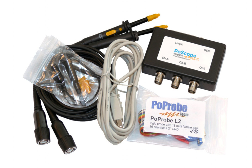
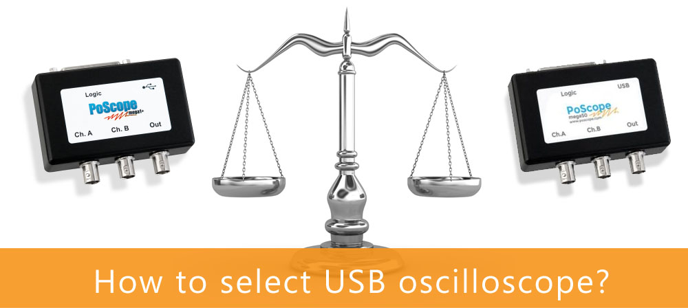
The evolution of USB oscilloscopes has fundamentally transformed how engineers and technicians approach electronic measurements. These compact yet powerful instruments represent a paradigm shift from traditional benchtop oscilloscopes, offering unprecedented flexibility without sacrificing critical functionality. The rise of USB oscilloscopes mirrors the broader trend toward portable, computer-connected test equipment that delivers professional-grade performance at accessible price points.
The Architecture of Modern USB Oscilloscopes
At their core, USB oscilloscopes consist of two primary components: a compact acquisition unit and sophisticated host software. This separation of hardware and processing power enables remarkable versatility. The acquisition module handles signal conditioning and analog-to-digital conversion, while the connected computer provides the display interface, measurement tools, and storage capabilities. This architecture allows USB oscilloscopes to leverage the continuous improvements in PC processing power, ensuring users always have access to advanced analysis features through software updates rather than hardware replacements.
The signal path in a USB oscilloscope follows an optimized design to maintain signal integrity despite the compact form factor. High-quality input protection circuits safeguard against overvoltage conditions, while precision analog front-ends ensure accurate signal acquisition. The digital section employs high-speed USB interfaces, with modern implementations using USB 3.0 or even Thunderbolt connections to handle the substantial data rates required for high-resolution waveform capture.
Practical Advantages in Real-World Applications
USB oscilloscopes excel in scenarios where traditional instruments prove cumbersome. Field service technicians appreciate their portability when troubleshooting industrial equipment on-site. Research scientists value their ease of integration into automated test systems, where the USB interface simplifies remote control and data logging. Educators find them ideal for laboratory environments, allowing students to analyze waveforms on their own laptops while keeping costs manageable.
The flexibility of USB oscilloscopes shines in unconventional measurement scenarios. Engineers working on embedded systems can easily transport their oscilloscope between lab and production environments. Automotive technicians diagnose vehicle electronics by powering the scope from a laptop battery, eliminating ground loop issues common in benchtop setups. The ability to save complete measurement sessions as project files further enhances workflow efficiency, enabling engineers to revisit and analyze data long after the initial measurement.
Performance Considerations and Limitations
While USB oscilloscopes offer compelling advantages, understanding their limitations ensures appropriate application selection. Bandwidth and sample rate specifications require careful evaluation against measurement needs. The distributed architecture introduces potential latency in waveform updates compared to dedicated benchtop instruments, though this gap continues to narrow with advancing interface technologies.

Power users should consider the implications of host computer performance on measurement stability. Complex math functions or deep memory acquisitions may strain older computers, potentially affecting real-time performance. However, these trade-offs are increasingly mitigated by modern computing power and optimized software design, making USB oscilloscopes viable for an ever-expanding range of professional applications.
The Future of USB-Based Measurement
The trajectory of USB oscilloscopes points toward even greater integration with modern computing ecosystems. Emerging trends include cloud-connected analysis capabilities, where measurement data automatically syncs with collaborative engineering platforms. Artificial intelligence-assisted measurement interpretation represents another frontier, with host software potentially identifying signal anomalies or suggesting measurement configurations based on the connected circuit.
As the boundaries between traditional test equipment and computer-based analysis continue to blur, USB oscilloscopes stand poised to redefine expectations for accessible, high-performance electronic measurement. Their continued evolution promises to further democratize advanced oscilloscope capabilities, putting professional-grade tools within reach of engineers at all levels and in all environments.
From Setup to Precision: How PoKeys57CNC and Mach4 Revolutionize CNC Control
Powering Precision: The Essential Role of Stepper Motor Drivers in Modern Systems
Understanding Measurement Instruments and Their Key Applications in Modern Electronics
